LOGIC GATES
We are familiar with basic addition and subtraction operation. There are also many other functions that digital systems are able to perform with the help of logic gates.
- Logic Gates can be used to implement large complex systems.
- Digital Logic Gates are identified by unique symbols. These symbols are used in circuit diagrams. Circuit diagram in whole define the function of a digital circuit.
- Digital Logic Gates function can be represented by the followings;\
- Boolean expression
- Truth table / Function table
- Logic circuit diagram
What is truth table?
Truth table is a table that stores inputs values and output after performing the operation on given inputs.
What is example of truth table?
Following table shows truth table for NOT Gate.
| Input | Output |
| o | 1 |
| 1 | o |
What are boolean expressions?
Some symbols and operators are used to represent the given inputs and output.
What are some examples of boolean expressions?
| Operator | Meaning | Expression |
| + | OR | X+ Y |
| * | AND | X AND Y |
What is logic circuit diagram?
Logic circuit diagram is a graphical representation of given inputs and outputs.
What is example of logic circuit diagram?
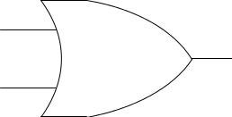
The three fundamental Gates are the AND, OR and NOT Gates and further classified as mentioned below;
- NAND
- XOR
- XNOR